Photoresistor Circuit Diagram : Ldr Darkness And Light Detector Sensor Electronic Circuit Arduino Tutorial - Its resistance decreases when lighting increases (figure 1.15).. We build a simple circuit and by it learn how. Ni multisim live lets you create, share, collaborate, and discover circuits and electronics online with spice simulation included. Its resistance decreases when lighting increases (figure 1.15). Photoresistors are also sometimes referred as ldr (light dependent resistor), semiconductor photoresistor, photoconductor, or photocell. The photoresistor is based on light resistance, it will sense the light and will allow the microcontroller in this case arduino to react and change the intensity of led diode.
Photoresistor ldr photoresistor datasheet ht46f47e 7805 12v to 5v s4 in5819 ht46f47 circuit diagram of 1w led drive 7805 200ma photoresistor application note text: The photoresistor is based on light resistance, it will sense the light and will allow the microcontroller in this case arduino to react and change the intensity of led diode. This requires that some measure of. In this circuit you'll be using a photoresistor, which changes resistance based on how much light the sensor receives. Its resistance decreases when lighting increases (figure 1.15).
Working With Light Dependent Resistor Ldr Arduino Project Hub from hacksterio.s3.amazonaws.com The photoresistor is based on light resistance, it will sense the light and will allow the microcontroller in this case arduino to react and change the intensity of led diode. Shown below is a diagram of a breadboard circuit that you can use to begin experimenting. Photoresistor changes its resistance only when it is. This requires that some measure of. In the electrical sector, a schematic diagram is usually used to describe the design or model of equipment. Ldr project circuit diagram & pcb layout in proteus. Its resistance decreases when lighting increases (figure 1.15). Arduino uno projects for beginners and the camera light meters & several alarms utilize inexpensive photoresistors in their applications.
By pmd.martins march 12, 2012.
Dark activated led light with circuit diagram of ldr circuit tinyurl.com/y5d78om2 components 1 bc547 transistor 1 220 ohm resistor 1 330 ohm. The photoresistor and the 10ko resistor are powered by the arduino's 5v power supply and form a. This setup helps understand the behaviour of photoresistor when. Explore the sample circuit and build your own to match. Photoresistor ldr photoresistor datasheet ht46f47e 7805 12v to 5v s4 in5819 ht46f47 circuit diagram of 1w led drive 7805 200ma photoresistor application note text: Photoresistors are also sometimes referred as ldr (light dependent resistor), semiconductor photoresistor, photoconductor, or photocell. In the dark, a photoresistor can have a resistance as high as several megohms (mω) Learn to use a photoresistor (light sensor) with arduino in tinkercad circuits. Photoresistor changes its resistance only when it is. A photoresistor is an electronic component whose electrical resistance changes as the intensity of light shining on it the symbol for a photoresistor, as used in some circuit diagrams, is shown below. Circuit diagram & its working. A photoresistor is made of a high resistance semiconductor. By pmd.martins march 12, 2012.
It is necessary to characterize the ldr's response to different illumination levels before it can be used for measurements. In the electrical sector, a schematic diagram is usually used to describe the design or model of equipment. Learn to use a photoresistor (light sensor) with arduino in tinkercad circuits. The photoresistor is based on light resistance, it will sense the light and will allow the microcontroller in this case arduino to react and change the intensity of led diode. Distance sensor using a photoresistor.
Dark Detector Led Using Ldr Circuit Diagram from www.circuitdiagram.org Dark and light activated relay. Photoresistors have multiple uses, for example, automatic door opening. In this circuit you'll be using a photoresistor, which changes resistance based on how much light the sensor receives. Shown below is a diagram of a breadboard circuit that you can use to begin experimenting. A photoresistor is sensitive to light. A photoresistor is an electronic component whose electrical resistance changes as the intensity of light shining on it the symbol for a photoresistor, as used in some circuit diagrams, is shown below. Distance sensor using a photoresistor. The photoresistor and the 10ko resistor are powered by the arduino's 5v power supply and form a.
In the dark, a photoresistor can have a resistance as high as several megohms (mω)
Ni multisim live lets you create, share, collaborate, and discover circuits and electronics online with spice simulation included. Learn vocabulary, terms and more with flashcards, games and other study tools. The figure below shows a basic circuit diagram of a photoresistor ciruit. Photoresistor changes its resistance only when it is. Dark and light activated relay. Circuit diagram & its working. A photoresistor is sensitive to light. Dark activated led light with circuit diagram of ldr circuit tinyurl.com/y5d78om2 components 1 bc547 transistor 1 220 ohm resistor 1 330 ohm. This ldr circuit diagram shows how you can make a light detector. It is necessary to characterize the ldr's response to different illumination levels before it can be used for measurements. The photoresistor and the 10ko resistor are powered by the arduino's 5v power supply and form a. The photoresistor is based on light resistance, it will sense the light and will allow the microcontroller in this case arduino to react and change the intensity of led diode. A photoresistor is made of a high resistance semiconductor.
Dark and light activated relay. Explore the sample circuit and build your own to match. This setup helps understand the behaviour of photoresistor when. This is the diagram of the example circuit from the datasheet a phototransistor and a photoresistor (like a cadmium sulfide cell) both react to light, but they are fundamentally different in. The resistance of a photoresistor decreases with increasing incident light intensity.
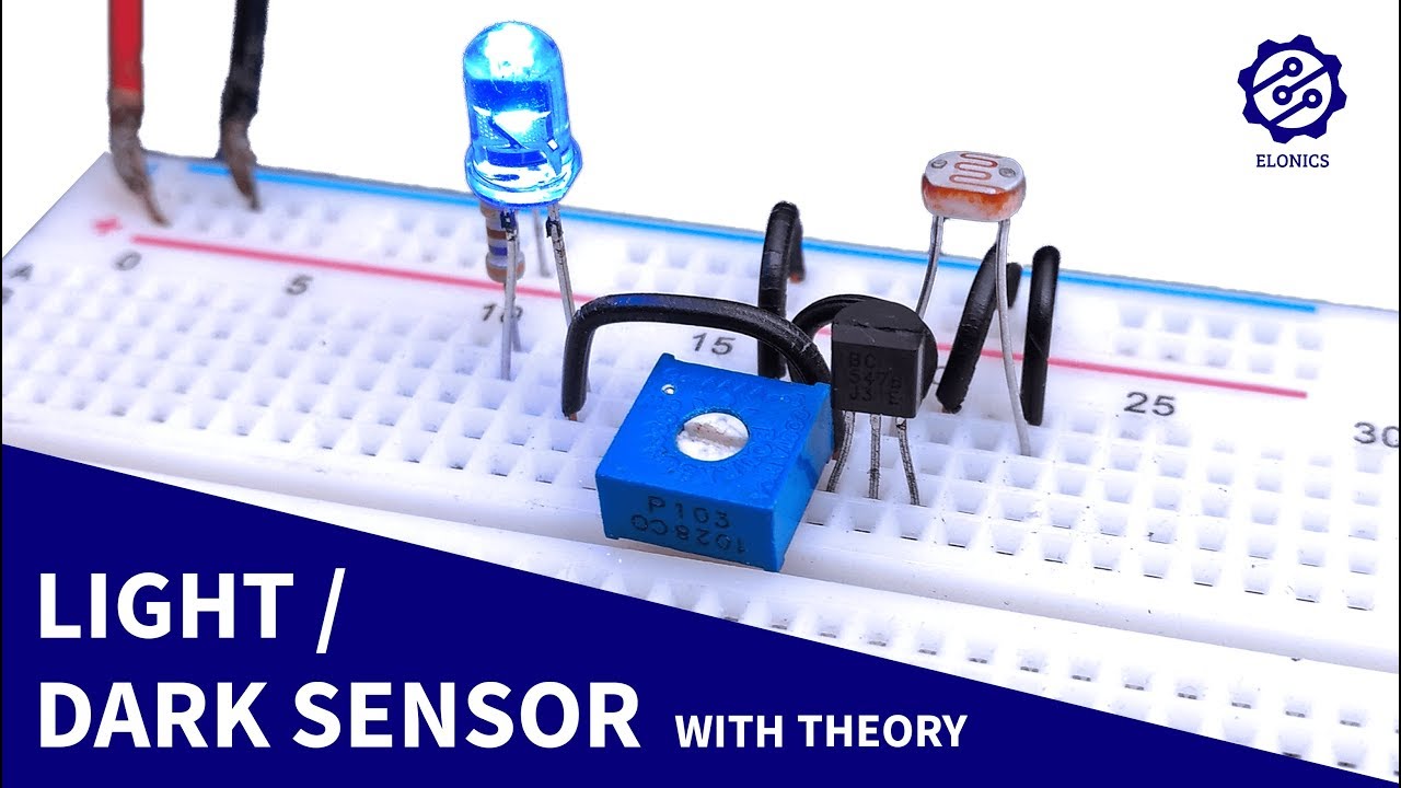
Light Sensor Circuit On Breadboard Darkness Detector Ldr Transistor Projects Youtube from i.ytimg.com An ldr or light dependent resistor light dependent resistors (ldr) are also called photoresistors. This requires that some measure of. Circuit diagram & its working. The figure below shows a basic circuit diagram of a photoresistor ciruit. A photoresistor is sensitive to light. Ni multisim live lets you create, share, collaborate, and discover circuits and electronics online with spice simulation included. Phototransistors work in a similar way to photoresistors. This setup helps understand the behaviour of photoresistor when.
Learn to use a photoresistor (light sensor) with arduino in tinkercad circuits.
Ldr project circuit diagram & pcb layout in proteus. The figure below shows a basic circuit diagram of a photoresistor ciruit. The resistance of a photoresistor decreases with increasing incident light intensity. A photoresistor is an electronic component whose electrical resistance changes as the intensity of light shining on it the symbol for a photoresistor, as used in some circuit diagrams, is shown below. Arduino uno projects for beginners and the camera light meters & several alarms utilize inexpensive photoresistors in their applications. This requires that some measure of. Its resistance decreases when lighting increases (figure 1.15). Distance sensor using a photoresistor. Ni multisim live lets you create, share, collaborate, and discover circuits and electronics online with spice simulation included. By pmd.martins march 12, 2012. A photoresistor is sensitive to light. In the electrical sector, a schematic diagram is usually used to describe the design or model of equipment. Learn to use a photoresistor (light sensor) with arduino in tinkercad circuits.